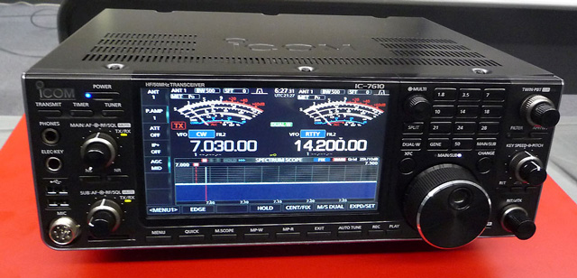

- ICOM 756 PRO II NO TX MANUALS
- ICOM 756 PRO II NO TX SERIAL
- ICOM 756 PRO II NO TX UPGRADE
- ICOM 756 PRO II NO TX FULL
But if there were more slots, it seems as if I would need to add 6 or so filters to be able to get the SSB and CW selectivity choices I would like. Of course this is not even possible because the has a single filter slot at each IF frequency.
ICOM 756 PRO II NO TX UPGRADE
In fact, given the cost difference between the two radios, I think that both are well worth their respective prices.įor me, I decided that the upgrade cost made sense because of the equivalent cost of the filters necessary to turn a into a PRO. I really do not want to give the impression that either radio is bad. Because I am comparing two radios here, it may appear as if one is good and one is bad. A few of my observations are contained at the end of this page.

Bj notes mbbsĪs of this writing, the radio is still quite new, and comments and observations are just starting to emerge. If you have any of your own observations, please email me, and I will add them to the list if appropriate. Newer Post Older Post Home.This gave me an opportunity to compare both radios side-by-side. The end result was awesome One of the pics here is the filter as modeled in software, the violet curve is before mods, the white curve is after mods. This moves the knee of the filter from 5.
ICOM 756 PRO II NO TX MANUALS
I checked the manuals and board layouts against each other, and while the filter units in the standard and Pro II are physically a little different, the circuit was the same. He came up with a few capacitor changes to alter the upper end of the filter response to fix the problem in the Pro II. He had access to some filter design software, and modeled the 80m filter to see where the problem was. Here's the info for the first phase of the modification I found that the band matrix is setup to use the 80m low pass filter up to 6.Īnother ham I was talking to on the internet had the IC Pro II and modified his for 60m coverage as I did, and had the same problem with low output power.
ICOM 756 PRO II NO TX SERIAL
Icom 756 Pro 3 Serial Numbersįluctuating RF output. The symptoms can be one or more of the following: Unusually high current demand from the power supply. Reduce power to 10 watts, then increase power after tuning.
ICOM 756 PRO II NO TX FULL
Running full power during antenna tuner adjustment.

Lightning surge, precipitation static, or static buildup on the antenna. This may help protect against RF-overload from a nearby transmitter. NOTE: The previous two photos depict an extreme and rare example. While he was transmitting from his other station, his wife alerted him to smoke coming from his ICPRO in another room. NOTE: The following two photos depict an extreme and rare example. The pictures below show a worst-case scenario. The collector voltage should be around If left unchecked, the situation may deteriorate until the damaged SMD components overheat and become charred, possibly damaging the circuit-board. The base voltage should be 0-volts RX, and 0. This test works because the attenuator interrupts the path of oscillation. The symptoms can be one or more of the following. This will not affect the 2-meter band on the series. But many times, the only noticeable issue is the transmitter will tend to oscillate intermittently on the higher HF bands 6, 10, or 12 meters. Important Note: Although I have first-hand knowledge of the damaged circuitry and the necessary repairs, I only have second-hand knowledge as to the cause of damage, which was acquired by interviewing customers about their station setups and operating practices. You should be aware of the fact that transmitter is set to transmitt on amateur bands only band-pass filtersso transmitting outside of those frequencies have to be with limited power only, or you can easily demage the transmitter!Sometimes, components on the RF Unit may also be affected. Of course, transmitting outside the amateur frequencies are not allowed neither for licenced radio amateurs! It will restart automatically and voila! The transmitter is "unloicked" now, and will be able to transmitt on all frequencies from about 0. After you have removed diodes as shown on above pictures, return the DSP-module, return the botom cover into its place and turn on the transceiver. Nonton film indonesiaĬarefully using a magnifying glass you should remove the diodes located at the PCB as shown on the picture below. Carefully unplug DSP-unit and place it aside. There is DSP-unit plug in metal box on the right side. Place the transceiver on the table with face toward you, upside down. This modification allows transmitter to transmit on whole frequency range. Transmitter is factory limited to transmit on amateurs bands only. It can receive from 30 kHz up to 60 MHz continuously and transmit all mode, all bands with watts RF power output.


 0 kommentar(er)
